
HVAC Controls Fundamentals
Understanding HVAC controls fundamentals is what helps everything else in the system make sense. Refrigeration creates the heat transfer, airflow moves the air, and electrical components provide power, but controls are what tell the system when, how much, and how often to respond.
Let’s start with a free practice test to see where you are at;
In modern HVAC, controls are what connect sensors, controllers, actuators, valves, dampers, and equipment into one working process. Without controls, the system would not know when to open a valve, modulate a damper, turn on cooling, reduce heating, or hold a target temperature.
This page breaks down the basics behind common control signals, pneumatic and electronic control, control loops, setpoints, BAS systems, PID concepts, and some simple control-related troubleshooting.
Why HVAC Controls Matter
HVAC controls exist to maintain a desired condition. That condition might be temperature, pressure, humidity, airflow, or another measured value. The controls system constantly compares actual conditions to the desired conditions and then adjusts the output to bring the system back where it belongs.
A basic understanding of HVAC controls fundamentals helps you:
- Understand what control signals mean
- Read 4–20 mA and 3–15 PSI signals more confidently
- Understand what a control loop is doing
- Recognize what a setpoint represents
- See how controllers, sensors, and actuators work together
- Troubleshoot why a valve, damper, or actuator is not responding properly
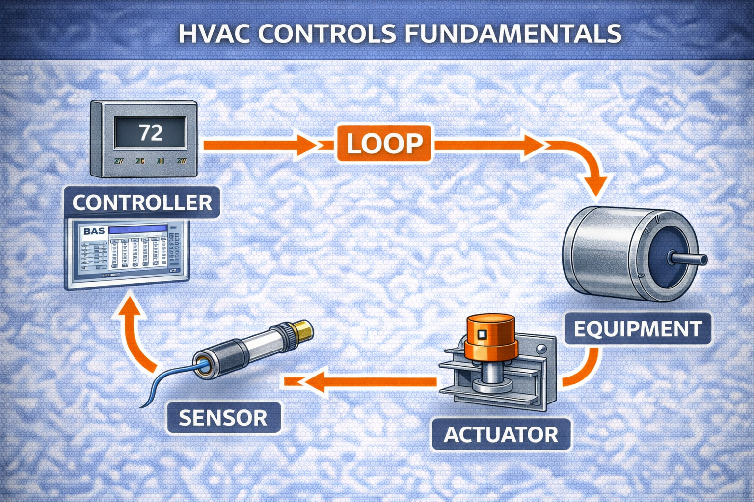
Controls work best when you think of them as a conversation:
- the sensor reports what is happening
- the controller decides what should happen
- the actuator or final device makes the adjustment
4–20 mA Signals Explained
What does a 4–20 mA signal represent?
A 4–20 mA signal is a current signal used for control.
It is one of the most common standard control signals used in HVAC, industrial controls, and process systems. Instead of sending a voltage signal, the control system sends current through a loop.
Why use current instead of voltage?
A major advantage of current signals is that they are less affected by electrical noise and distance than voltage signals.
That makes them very useful in larger systems where sensors and actuators may be located far apart or where electrical interference could cause false readings.
Why is 4 mA used instead of 0 mA?
The reason 4 mA is used as the minimum instead of 0 mA is because it helps detect signal loss or a broken wire.
If a system is designed so that normal minimum signal is 4 mA, then a reading of 0 mA usually tells you something is wrong, such as:
- an open circuit
- broken wire
- failed loop
- lost power in the signal path
This is one of the most practical ideas in controls because it makes fault detection easier.
What does 20 mA usually represent?
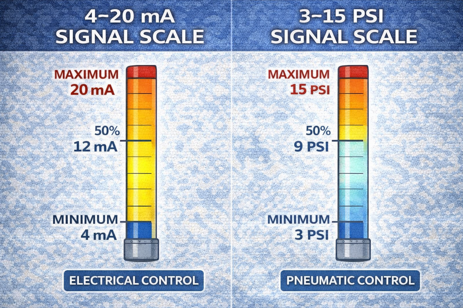
In a standard 4–20 mA loop, 20 mA typically represents maximum signal value.
That means the loop has a range:
- 4 mA = minimum
- 20 mA = maximum
What does 12 mA usually mean?
If a sensor reads 12 mA, that generally means 50% signal.
That is because 12 mA sits halfway between 4 and 20 mA in the operating range.
A quick way to think of it:
- 4 mA = 0%
- 12 mA = 50%
- 20 mA = 100%
Pneumatic Signals: 3–15 PSI
What does a 3–15 PSI signal represent?
A 3–15 PSI signal is a pneumatic control signal.
These signals were widely used in older control systems and are still found in some buildings today. Instead of using electricity as the output signal, the system uses compressed air pressure to represent the control command.
What does 3 PSI represent?
In a 3–15 PSI system, 3 PSI represents the minimum control signal.
What does 15 PSI represent?
In the same system, 15 PSI represents the maximum control signal.
So just like the 4–20 mA range, pneumatic controls also have a minimum and maximum working span:
- 3 PSI = minimum
- 15 PSI = maximum
This gives the controller a way to position devices such as dampers and valves across a full range rather than simply on or off.
Transducers: Converting One Signal to Another
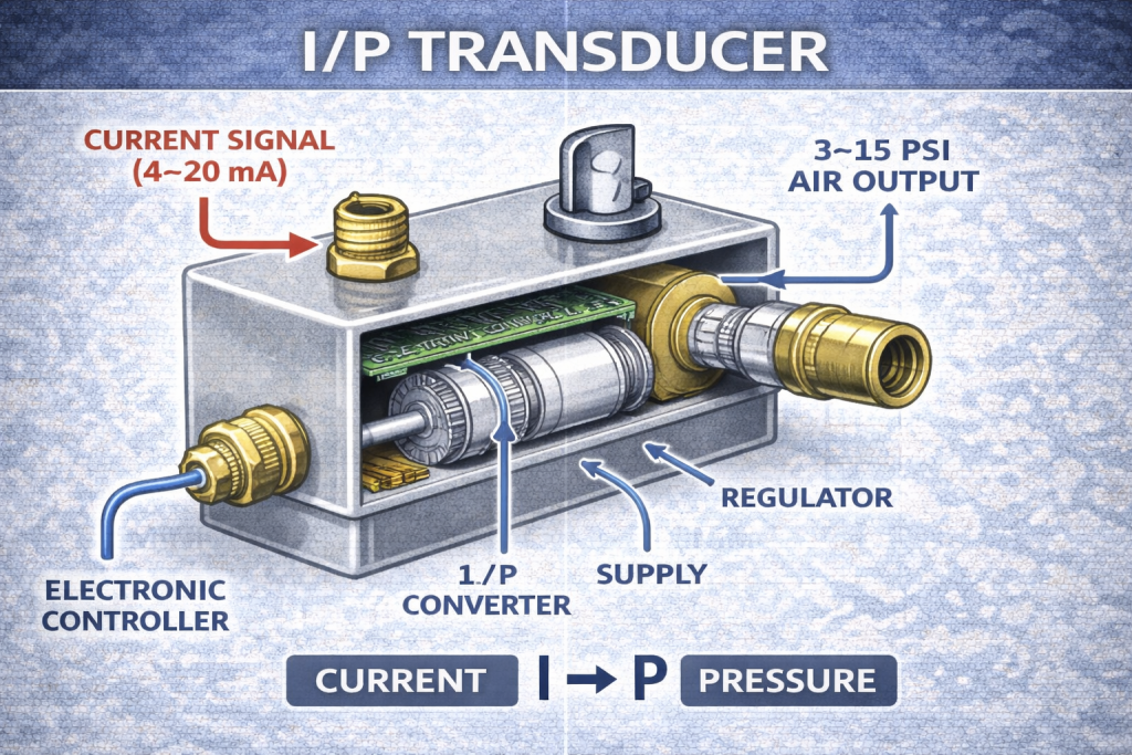
What does an I/P transducer do?
An I/P transducer converts a 4–20 mA electrical signal into a 3–15 PSI pneumatic signal.
The letters help:
- I = current
- P = pressure
This allows an electronic controller to operate a pneumatic device.
What does a P/I transducer do?
A P/I transducer converts pressure to current.
That means it takes a pneumatic input and creates an electrical output signal that can be used by a control system.
These devices are important because many buildings contain a mix of older pneumatic hardware and newer electronic control systems.
Control Loops and Control Logic
What is a control loop?
A control loop is the continuous process of measuring and adjusting a variable.
This is one of the biggest concepts in controls.
A simple control loop works like this:
- A sensor measures a condition
- The controller compares that condition to the setpoint
- The controller sends an output signal
- The final control device responds
- The system changes
- The sensor measures again
That repeating feedback process is what allows a system to maintain stable conditions instead of just turning fully on or off at random.
What is a controlled variable?
A common example of a controlled variable is temperature.
Other controlled variables could include:
- pressure
- humidity
- airflow
- level
- carbon dioxide
- position
The important idea is that the control system is always trying to manage something measurable.
What is a setpoint?
A setpoint is the desired value of a controlled variable.
If the controlled variable is room temperature, then the setpoint might be 72°F.
If the variable is duct static pressure, the setpoint might be a certain pressure level.
If the variable is chilled water temperature, the setpoint is the target value the controller is trying to maintain.
Sensor above setpoint
If a temperature sensor reads above setpoint, the system should usually reduce heating or increase cooling.
That is the core logic of automatic control:
- compare actual value to desired value
- adjust output to reduce the difference
Valves, Actuators, and Final Control Devices
Valve stuck fully open
If a control valve is stuck at 100% open, one likely cause is that the signal is stuck at maximum.
That means the controller or signal path may be continuously commanding full output.
20 mA at controller, but valve stays closed
If you measure 20 mA at the controller, but the valve is still closed, the most likely issue is a faulty actuator or mechanical failure.
This is an important diagnostic point:
- if the signal is correct
- but the device does not respond
- then the problem is likely not in the controller output
At that point, you start suspecting:
- bad actuator
- stuck linkage
- mechanical binding
- failed valve body
- disconnected final device
BAS Systems
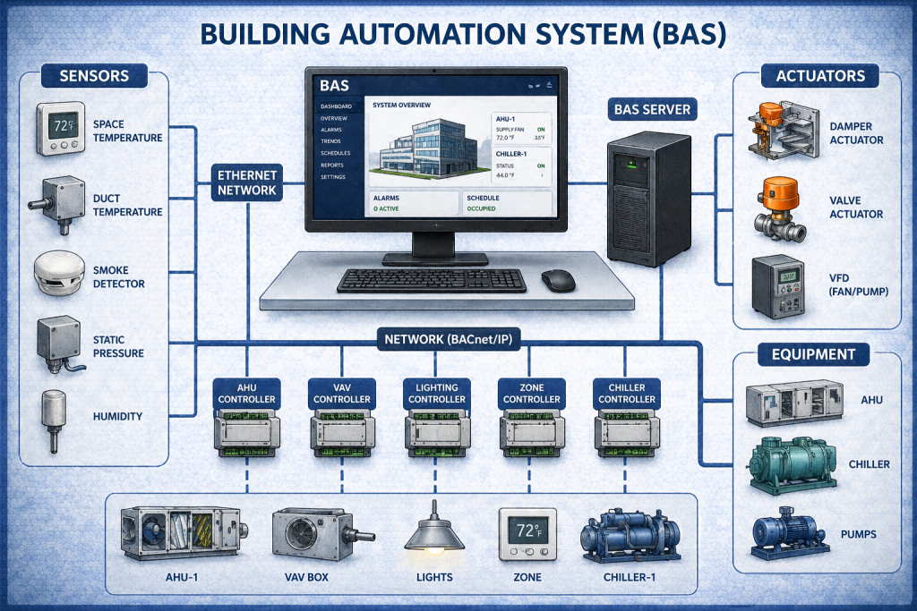
What is a BAS system?
BAS stands for Building Automation System.
A BAS is a centralized system used to monitor and control HVAC equipment and other building functions. It allows operators to:
- monitor temperatures
- adjust schedules
- trend system data
- alarm faults
- manage energy use
- control multiple pieces of equipment from one interface
In many modern buildings, BAS is the platform that ties all of the sensors, controllers, valves, dampers, and sequences together.
PID Control Basics
What is the purpose of a PID controller?
A PID controller is used to maintain stable control by adjusting output.
PID stands for:
- Proportional
- Integral
- Derivative
You do not need to master the math right away to understand the purpose. The basic idea is that PID helps the system avoid being too slow, too aggressive, or too unstable.
A good PID response helps a system:
- reach setpoint smoothly
- avoid hunting
- avoid wide swings
- stay stable under changing conditions
For beginners, it is enough to understand that PID helps the system make smarter adjustments instead of just reacting in a simple on/off way.
Calibration and Sensor Accuracy
What happens if a sensor is out of calibration?
If a sensor is out of calibration, it can cause incorrect system control decisions.
That is because the controller can only make good decisions if the input information is accurate.
A bad temperature sensor may make the system:
- overcool
- overheat
- cycle poorly
- waste energy
- drive valves or dampers to the wrong position
This is one of the most important control concepts:
bad input leads to bad output.
Common HVAC Controls Diagnostic Ideas
0 mA in a 4–20 mA loop
If a 4–20 mA loop reads 0 mA, the most likely issue is a broken wire or open circuit.
This ties directly back to why 4 mA is the normal minimum. A true 0 mA reading often points to a failure rather than a normal low reading.
Signal correct, device not moving
If the control signal is correct but the device does not respond, you start suspecting:
- failed actuator
- stuck valve
- damaged linkage
- mechanical binding
- failed pneumatic or electric final element
Device wide open all the time
If a valve or actuator remains at full output, look for:
- signal stuck high
- controller output forced
- calibration issue
- failed actuator spring return or linkage problem
How HVAC Controls Work Together
A simple controls sequence may look like this:
- A sensor reads the current condition
- That reading is sent to a controller
- The controller compares it to the setpoint
- The controller sends an output signal such as 4–20 mA
- A transducer or actuator receives the signal
- A valve, damper, or device adjusts position
- The system changes condition
- The sensor reads again and the loop continues
That repeating feedback cycle is the heart of HVAC controls.
Quick Review of HVAC Controls Fundamentals
Here is a simple recap of the biggest concepts:
- 4–20 mA is a current signal used for control
- 4 mA is used as the minimum so faults can be detected
- 20 mA usually represents maximum signal
- 12 mA is generally about 50% signal
- Current signals resist electrical noise and distance better than voltage
- 3–15 PSI is a pneumatic control signal
- 3 PSI is minimum signal and 15 PSI is maximum signal
- An I/P transducer converts current to pressure
- A P/I transducer converts pressure to current
- A control loop continuously measures and adjusts a variable
- Temperature is a common controlled variable
- A setpoint is the desired value of that variable
- If the temperature is above setpoint, the system should reduce heating or increase cooling
- BAS stands for Building Automation System
- PID control helps keep output stable
- An out-of-calibration sensor causes bad control decisions
- A 0 mA loop reading often means an open circuit
- If the signal is correct but the valve does not move, suspect actuator or mechanical failure
HVAC Quiz Preparation: What to Focus On
If you are preparing for the free or paid controls quiz, focus on understanding the relationships rather than just memorizing letters and acronyms.
Make sure you understand:
- Why 4–20 mA uses 4 instead of 0
- What minimum, midpoint, and maximum signal values mean
- The difference between electrical and pneumatic signals
- What an I/P or P/I transducer is doing
- What a control loop actually is
- What a setpoint means in the real world
- Why accurate sensors matter
- Why the output signal and final device both have to be checked in troubleshooting
Once those ideas click, controls stop feeling abstract and start feeling logical.
Final Thoughts
HVAC controls fundamentals are what tie the rest of the system together. Controls tell the system when to respond, how strongly to respond, and when to stop responding. Without controls, the equipment has no real intelligence or direction.
Once you understand common signals like 4–20 mA and 3–15 PSI, along with control loops, setpoints, transducers, actuators, BAS systems, and PID control, you build a foundation for much deeper troubleshooting and automation knowledge later on.
This stage is where HVAC starts to become more than parts and begins to feel like a complete system.
FAQ Section
What does a 4–20 mA signal mean?
A 4–20 mA signal is a current-based control signal commonly used in HVAC and industrial automation.
Why does 4–20 mA start at 4 instead of 0?
Starting at 4 mA makes it easier to detect broken wires or open circuits because 0 mA usually indicates a fault.
What does 12 mA mean in a 4–20 mA loop?
12 mA generally represents 50% of the signal range.
What is a 3–15 PSI signal used for?
A 3–15 PSI signal is used in pneumatic control systems.
What is an I/P transducer?
An I/P transducer converts electrical current into pneumatic pressure.
What is a control loop?
A control loop is the continuous process of measuring a variable and adjusting output to maintain the desired condition.
What is a setpoint?
A setpoint is the desired target value of a controlled variable.
What does BAS stand for in HVAC?
BAS stands for Building Automation System.
What does a PID controller do?
A PID controller adjusts output to help the system maintain stable control.