Acronym Legend:
- mA- Milliamp
- PID- Proportional Integral Derivative
- SCADA- Supervisory Control and Data Acquisition
- PLC- Programmable Logic Controller
- DC- Direct Current
- AC- Alternating Current
- HMI- Human-Machine Interface
- GPH- Gallons per hour
- pH- Power of Hydrogen
- ORP- Oxidation-Reduction Potential
Introduction:
4-20mA current loop is a DC loop that is the dominant standard of analog process control signals used to transmit process information in many industrial applications.
These loops are used to control and carry signals from field instruments to PID controllers, PLC cabinets and eventually reaching data systems like SCADA. It is the ideal method of transferring process information because current does not change as it travels from transmitter to receiver, much like water in your home; the flow is constant.
Origin:
Before electronic circuitry, process control was completely mechanical and therefor the standard was pneumatic control signals by air compression, ranged 3-15 psi. The reason it was 3-15 psi was because signals below 3 were unrecognizable and it was easier to differentiate a live zero (3 psi) from complete failure (0 psi), 15 was used to keep it easily divisible in percentage; 3 (0%), 6 (25%), 9 (50%), 12 (75%), 15 (100%).
In the 1950s when electronics became less expensive and more popular, current input became the more efficient and preferred standard.
Over the years there have been other loops used for applications as people experimented but the main ones were;
- 10-50mA because technology at those times used magnetic amplifiers which required a minimum 10mA to operate
- 4-20mA, which as you can tell both share the same divisional breakdown; 3 psi/10mA/4mA= 0%, 6 psi/20mA/8mA= 25%, 9 psi/30mA/12mA= 50%, 12 psi/40mA/16mA= 75%, and 15 psi/50mA/20mA= 100%
These current values were also used because they corresponded to 1-5V analog voltage across a 250 Ohm resistor, making it easy to adapt the 4-20mA current loop to a 1-5VDC analog input voltage as well.
Current, like water flow, can be restricted, while water is restricted by pipe size reduction, current is restricted by resistance, these resistors are placed strategically in line to reduce the current and alleviate the chance of equipment getting fried. Even with resistance, current flow is still constant, which is why current loop is recommended over voltage analog.
This is why using current as a means of conveying process information is so reliable, it is kept low and sufficient so there is rarely a significant drop.
The reason for the minimal value (3 psi, 4 mA, 10mA) is because it should be enough to drive the minimal requirements of devices and still be able to differentiate a “live-zero” and real loss of energy. Since all require a minimum of 3 mA to power up and 4 is nothing more than a value transmitted, when you receive the 3.5-4mA, it shows that you still have power and that value is live, anything less would show a disruption in the power supply, like loss from provider, cable cut or tripped breakers.
The reason 20mA was used as the maximum is stated to be because the human heart can withstand up to 30mA of current, so as a safety point of view, 20mA was chosen.
In choosing their minimum and maximum, it was realized the originators wanted to stay in the parameters of 3-30mA, and with wanting to stay linear with base value, the only options present were 4-20 or 5-25. Since calculations are easier in multiples of 2, 4-20mA had more votes, thus 4-20mA is what we get.
Current loop steps
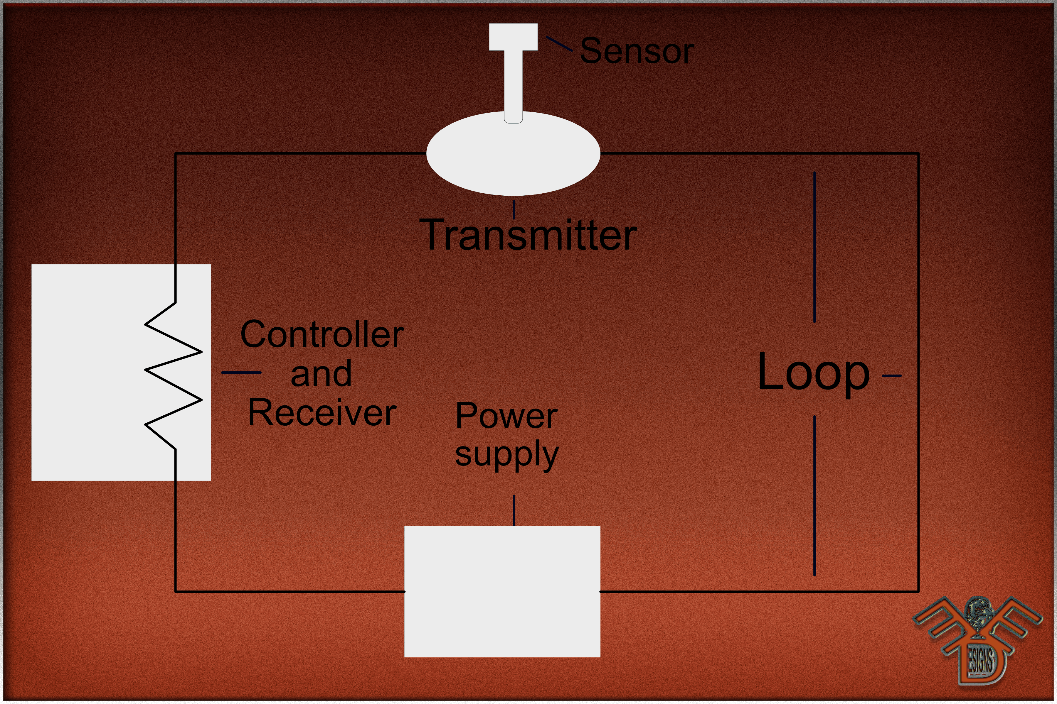
The 4 steps and requirements necessary to make a 4-20mA loop are;
Power Source
The most common DC power source for 4-20mA is 24V but it has been used with 12V, 15V and even 36V since some older systems used higher voltage. The reason DC is used over AC is the magnitude of the current, with DC being constant and AC continuously changing, making it difficult for the signal level to transmit. With that in mind, the power supply must be greater than the sum of the minimum voltage required to operate the transmitter, plus the IR drop of the Receiver, and in the event of long transmission runs, the IR drop in the wire.
When calculating that drop, consider the maximum level of the current that can flow through the 4-20mA loop, not just your 20mA value, but the over-scale or alarm limit of the transmitter.
Sensor
The device used for measuring the process variable; commonly being temperature, humidity, valve position, motor speed, flow, pH, ORP, Ammonia, level, and/or pressure
Transmitter
This is the key for transmitting the 4-20mA signal from the sensor to the controller, conveying the real world signal of flow, speed, pressure, etc. into a control signal necessary to regulate the flow of current in the loop. It takes that signal the sensor gives it and converts it to the 4-20mA source that the controller can understand; 4mA being the 0 to 20mA being the 100% of what the scaling/span is.
The transmitter only uses what it needs to convert the measurement, it causes the drop mostly requiring the resistor in the controller.
Receiver/Controller
This device is at the other end of the transmission line, receiving that transmitted signal. This unit itself can be any number of different devices, such as; panel meter, PLC, motor speed control, or some other digital control system like SCADA or BACTALK that you span to the process; 0-X feet, 0-X degrees, 0-X gallons per hour, etc. “X” being whatever you program as the maximum capacity that your instrument will read.
It reads the output that the transmitter gives it and either displays it itself in a simple form so operators can say or it stores the info in a database for trends, for example; if you have a tank that is 30 feet and you set a span of 0-30, the sensor sends a signal which the transmitter converts to 12mA, the control system will reflect 15 feet since the 12mA is 50% of the set-point. It will either show this level on a display of some sort or add it to a software trend-log for future reference.
The span importance is high, the local field span should be the same as the span on the analog card for accurate results.
Here are some examples of uses;
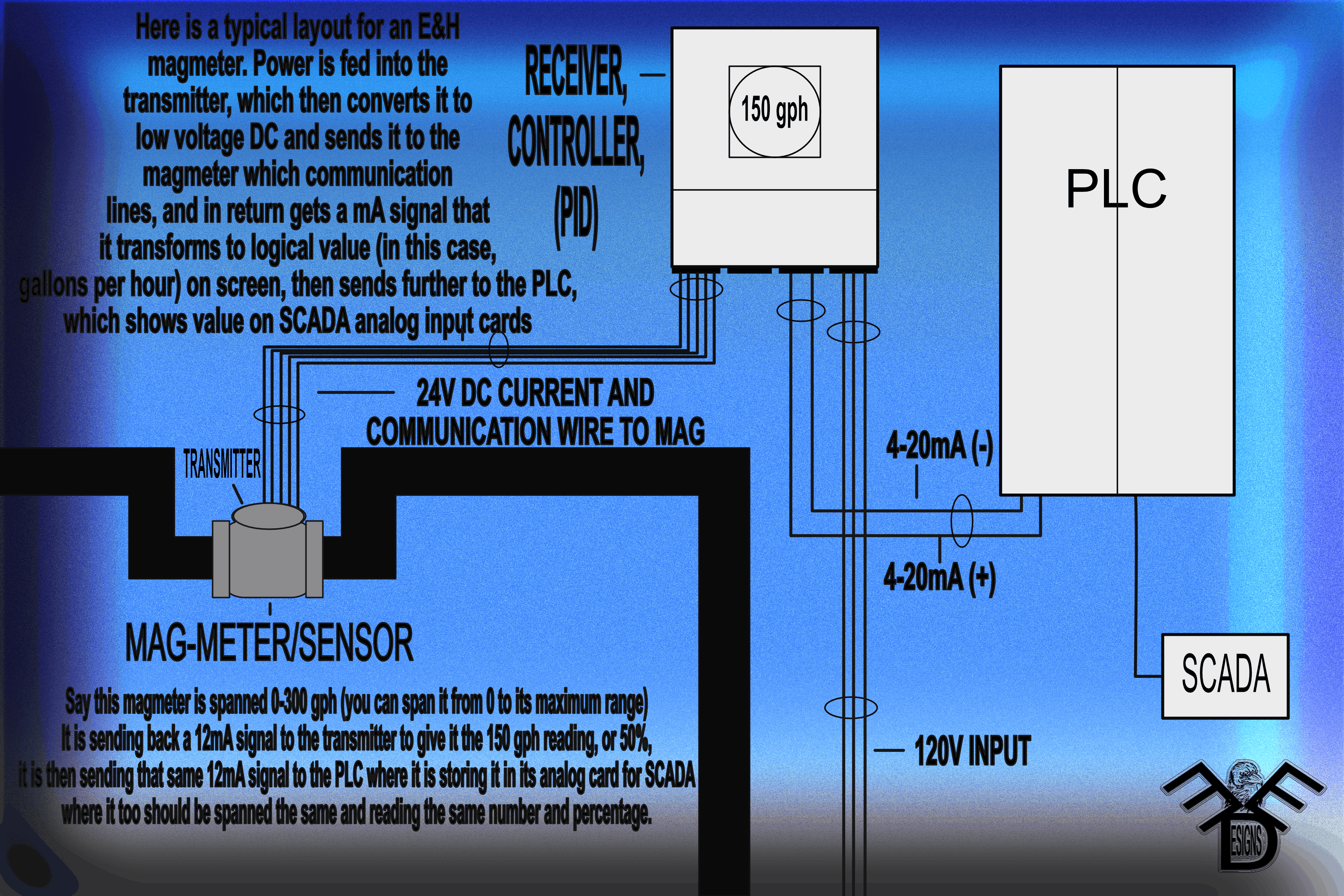
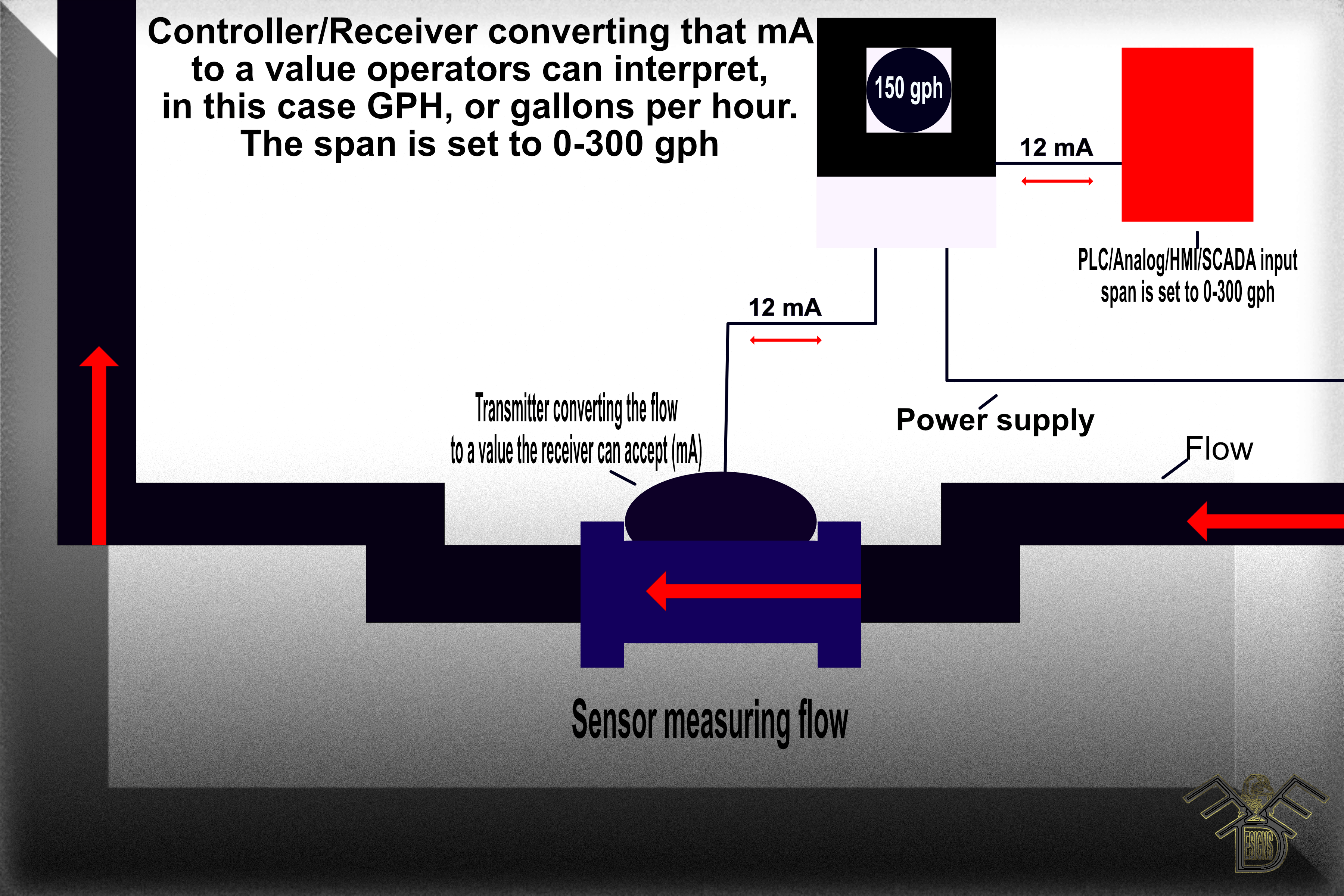
- You have a powered local controller spanned 0-300 GPH for a flowmeter, the flow-meter is transmitting 12mA back to the controller giving it a reading of 150 GPH, if that controller has an output source to an HMI, that will reflect the same value.
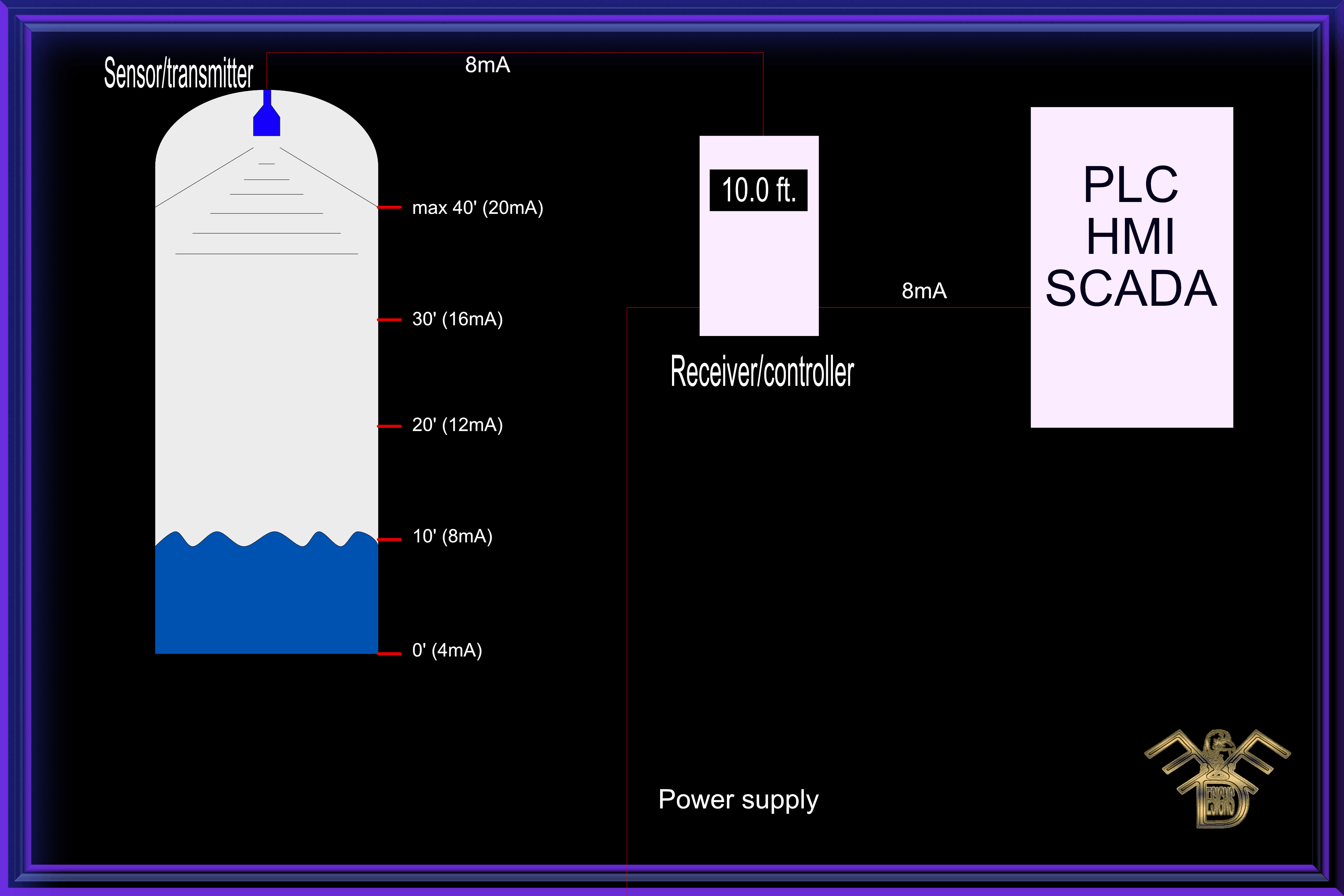
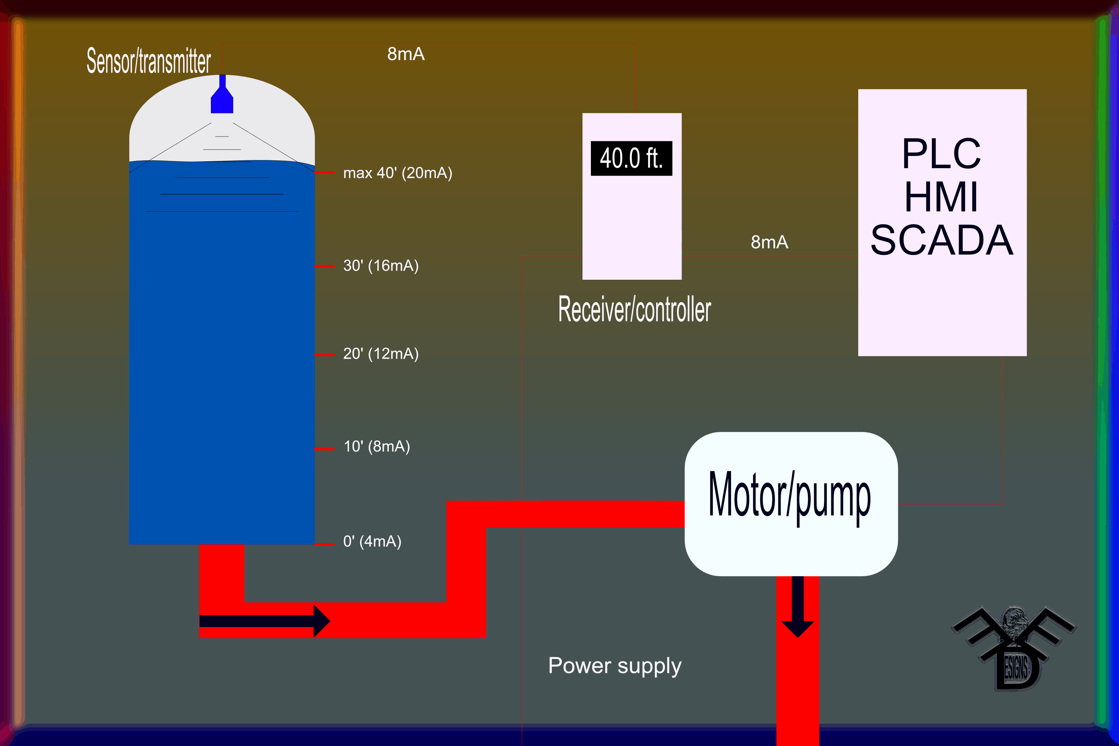
- You have a tank that is 40 feet deep so you span your controller for 0-40’ and place your transducer on it, it reads 10’, your controller is receiving an 8mA signal transmitted from the sensor.
4-20mA isn’t limited in just reading, it regulates too. Here is an updated photo of the level maxed out signaling an alarm at the PLC that calls for the motor to kick on and pump water out
The PLC stores analog and discreet cards for these purposes. The analog cards are spanned to go along with the 4-20mA ranges while the discreet cards go towards status such as motor running/not running, alarms active, valve opened/closed, etc. but they work together, for example a signal coming back high trips the alarm and tells the pump to come on through ladder logic programming on the software side of the PLC. If the full capacity of the pump isn’t required, or a valve doesn’t need to be fully open, you can set an analog to them as well to regulate how much flow should pass.
Same works with air conditioning; if you have an HVAC system linked with a span of 0-100 degrees and your thermostat is set at 71 degrees, it would show 15.36 mA, if you adjust it to 78 degrees, it would then send a 16.48 mA signal in that instance. The fan itself would be tied to the discreet to indicate on/off when temp is above/below the setpoint.
To go over again, the numbers represent the real value, in percentages, of the process once you have a minimum and maximum established. here is a breakdown of what those numbers mean in real value;
4-20mA;
4mA=0%, 8mA=25%, 12mA=50%, 16mA=75%, 20mA=100%
Likewise for the pneumatic 3-15psi;
3psi=0%, 6psi=25%, 9psi=50%, 12psi=75%, 15psi=100%
The analog cards work in spans of 0-X on various processes, they convey and convert the ranges from the field to the HMI or SCADA unit while the discreet works with the same, but only as status of on/off.