
Understanding 4–20mA Current Loops in Process Control
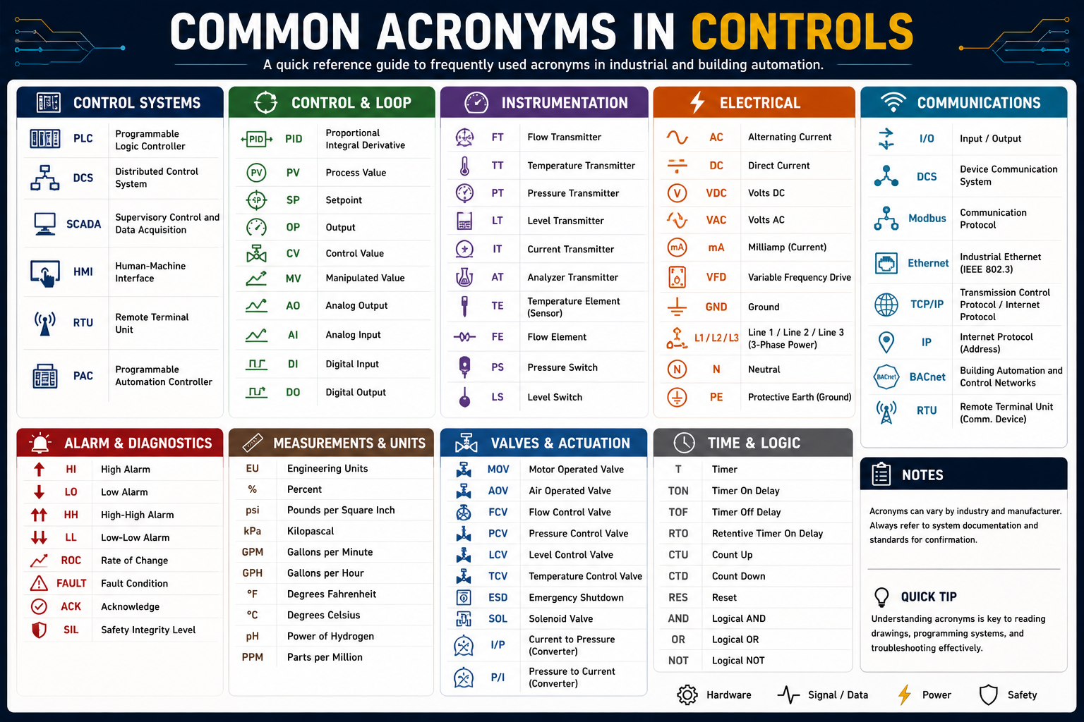
Acronym Legend
- mA – Milliamp
- PID – Proportional, Integral, Derivative
- SCADA – Supervisory Control and Data Acquisition
- PLC – Programmable Logic Controller
- DC – Direct Current
- AC – Alternating Current
- HMI – Human-Machine Interface
- GPH – Gallons Per Hour
- pH – Power of Hydrogen
- ORP – Oxidation-Reduction Potential
Introduction
The 4–20mA current loop is the industry standard for transmitting analog signals in process control systems.
It’s widely used because current remains stable over long distances, unlike voltage, which can drop due to resistance in wiring. This makes 4–20mA one of the most reliable and accurate ways to send data from field devices to control systems.
Simple Analogy:
Think of it like water flowing through a pipe:
- The flow (current) stays consistent
- Unless there’s a leak (fault or break in the loop)
Background & Evolution
Before electronic control systems, industries relied on pneumatic signals using compressed air:
Pneumatic Standard: 3–15 PSI
- 3 psi = 0%
- 6 psi = 25%
- 9 psi = 50%
- 12 psi = 75%
- 15 psi = 100%
The “live zero” (3 psi) allowed operators to detect failures (0 psi = broken system).
Transition to Electrical Signals
As electronics advanced (around the 1950s), current-based signals replaced air.
Several ranges were tested:
- 10–50mA
- 5–25mA
Eventually, 4–20mA became the standard because:
- Maintains a live zero (4mA)
- Matches the same % breakdown as pneumatics
- Easily converts to 1–5V using a 250Ω resistor
- Stays within a safe current range
- Provides clean, simple scaling
Why Current Instead of Voltage?
Voltage Signals:
- Drop over distance
- Affected by resistance and noise
Current Signals:
- Remain constant through the loop
- Resistant to electrical interference
- Reliable over long cable runs
As long as the loop is complete, the signal is accurate.
Components of a 4–20mA Loop
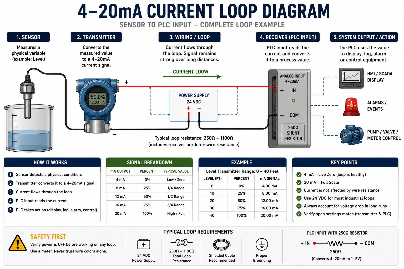
1. Power Supply
- Typically 24VDC
- Must overcome:
- Transmitter voltage drop
- Receiver resistance
- Wire resistance (especially long runs)
Always design for maximum loop current, not just 20mA.
2. Sensor
Measures a physical process, such as:
- Temperature
- Pressure
- Flow
- Level
- pH / ORP
- Humidity
- Speed
Converts real-world conditions into raw data.
3. Transmitter
Converts sensor data into a 4–20mA signal.
Example:
- Range: 0–300 GPH
- Measured: 150 GPH
Output = 12mA (50%)
Think of it as the translator between process and control system.
4. Receiver / Controller
Common devices:
- PLC input card
- SCADA system
- VFD
- Panel meter
- BAS (Building Automation System)
What it does:
- Displays values (HMI)
- Logs data
- Triggers alarms
- Controls equipment
Signal Breakdown
| Signal | Percent | Pneumatic Equivalent |
|---|---|---|
| 4mA | 0% | 3 psi |
| 8mA | 25% | 6 psi |
| 12mA | 50% | 9 psi |
| 16mA | 75% | 12 psi |
| 20mA | 100% | 15 psi |
Control Functions (Not Just Monitoring)
4–20mA signals don’t just display values—they control systems.
Example: Tank Level
- 20mA = Full tank
- PLC triggers pump
- Pump speed adjusts using analog output
Example: HVAC Control
- Setpoint: 71°F → ~15.36mA
- Setpoint: 78°F → ~16.48mA
System adjusts airflow or cooling accordingly.
Analog vs. Discrete Signals
Analog (4–20mA)
- Continuous values
- Example: temperature, flow, level
Discrete (Digital)
- On/Off signals
- Example: motor ON/OFF, valve OPEN/CLOSED
Working Together:
- Analog detects condition
- Discrete responds (turns equipment on/off)
- Analog output adjusts intensity (speed, position)
Key Concept: Span Matching
Your transmitter and controller must match ranges.
Example:
- Transmitter: 0–100 PSI
- Controller: 0–300 PSI
Result = incorrect readings
Common Troubleshooting Insights
- 0mA → Broken loop / power loss
- 4mA → Low end (or normal zero)
- >20mA → Fault or alarm condition
- Unstable signal → Noise or grounding issue
Why 4–20mA Still Dominates
- Simple and reliable
- Low power requirement
- Long-distance capable
- Noise-resistant
- Easy to troubleshoot
Bringing It All Together: Control Systems Through SCADA
Modern control systems don’t operate in isolation—they are part of a fully integrated network. At the center of that network is SCADA, the system that brings data, control, and decision-making together.
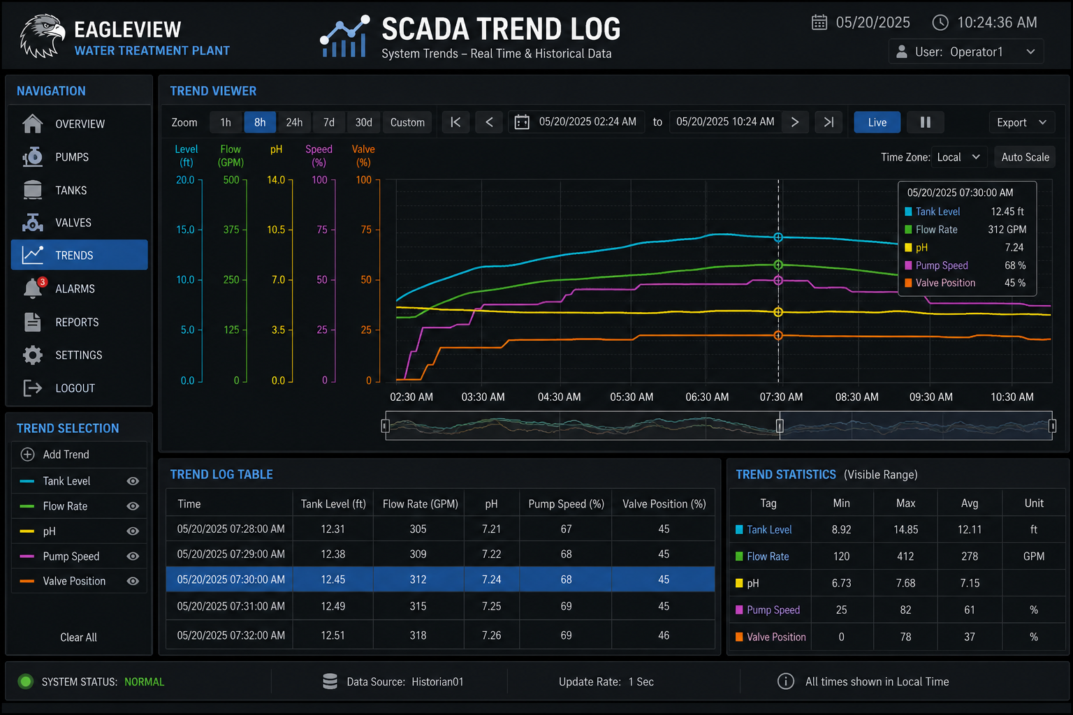
What SCADA Does
SCADA acts as the brain and dashboard of an entire operation. It collects data from the field, processes it, and gives operators the ability to monitor and control systems in real time.
Core Functions:
- Monitor → Displays real-time process values (level, flow, temperature, etc.)
- Log → Stores historical data (trend logs)
- Control → Sends commands to equipment
- Alert → Triggers alarms when conditions go out of range
How Everything Connects
Think of SCADA as the final layer in a chain:
The Control Loop in Action
- Sensor
Measures a real-world condition
(Level, pressure, temperature, flow) - Transmitter (4–20mA)
Converts that measurement into a signal - Controller (PLC / PID)
- Reads the signal
- Compares it to a setpoint
- Decides what action to take
- Output Device
- Valve opens/closes
- Motor speeds up/slows down
- Pump turns on/off
- SCADA System
- Displays everything
- Logs data
- Allows operator control
This is where everything you’ve learned—circuits, wiring, voltage, signals, and logic—comes together.
Real-World Example (Water System)
- Tank level sensor reads 50% → 12mA
- PLC receives signal and compares to setpoint
- If level is too high:
- PLC signals pump to turn on
- SCADA displays:
- Tank level rising/falling
- Pump status (ON/OFF)
- Historical trend over time
Operator can:
- Adjust setpoints
- Start/stop equipment
- Review system performance
Trend Logging (Why It Matters)
SCADA doesn’t just show what’s happening—it shows what happened.
Trend Logs Help You:
- Spot system inefficiencies
- Detect failures early
- Analyze performance over time
- Troubleshoot recurring issues
If you see a pump cycling too often, the problem isn’t just electrical—it’s system control.
Operator vs Technician Mindset
Operator Focus:
- Monitor screens
- Respond to alarms
- Adjust setpoints
Technician Focus:
- Trace signals (4–20mA, voltage)
- Verify wiring and components
- Diagnose why something isn’t working
SCADA shows the problem.
Skilled trades solve it.
Why This Matters
SCADA is used in:
- Water & wastewater treatment plants
- HVAC building automation systems
- Manufacturing facilities
- Power generation and distribution
- Oil & gas systems
Understanding SCADA means you understand:
Conclusion
The 4–20mA current loop remains the gold standard in industrial control because of its:
- Reliability
- Accuracy
- Simplicity
- Scalability
If you can:
- Read a SCADA screen
- Understand the signal behind it
- Trace it back to the field
You’re no longer just “working on equipment”
You’re understanding the entire system
From water treatment plants to HVAC systems to industrial automation, this signal method continues to be the backbone of modern control systems.
Final Takeaway
- 4mA = Alive (not zero)
- Current = Truth over distance
- Analog = Control, not just measurement
- Sensors collect data
- Signals carry information (4–20mA)
- Controllers make decisions (PLC/PID)
- SCADA shows and controls everything